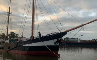
Recently EcoClipper had some exciting news – the company has been collaborating with Cape Horn Engineering to model different hull shapes for the EcoClipper500.
“Cape Horn Engineering was chosen by EcoClipper as a partner company to provide the design team with expert CFD analysis for the design of their first hull shape. An ambitious R&D programme was agreed and extensive CFD simulations for 4 different candidate hulls were performed and compared at different sailing conditions to aid the design process.”
– Read the full press release here.
What does this all mean? Why was this necessary when designing a ship? I talked to Naval Architect Francisco, who has been working on the EcoClipper ship, about the stages of trialling hull shapes.
Sidenote: this may get technical!
Why was it necessary to test different hull shapes?
EcoClipper’s vision is to up-scale the sail cargo industry by introducing larger sailing ships. Last year, it became apparent that the original Noach, of which the EcoClipper ship is based on, could be extended to maximise cargo space potential.
The simplest way to do this is to extend the original design. But this was a chance to test different hull shapes, to make sure that all other options had been approached.
What hull shapes were tested?
After designing six other hull shapes, each with specific changes, the team decided on putting four to the Cape Horn Engineering test. This blog will look at three of the hull candidates, as they illustrate the adopted design philosophy and solutions that EcoClipper wanted to see tested.
Hull 1 – the extended original design (not much deadrise)
The first hull shape was an extension of the original design. The image below shows the basic shape of this hull. The roundness of the hull in the top-right drawing shows that there is not much deadrise.
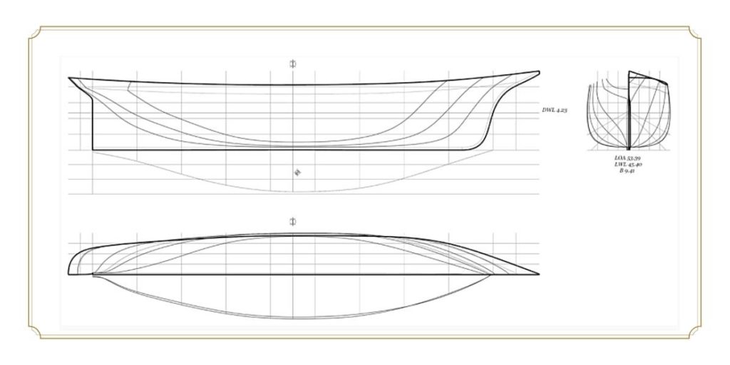
Deadrise: The deadrise of a boat is the angle measurement between the boat bottom and a horizontal plane on either side of the center keel.
This means that the ship is noticeably slightly rounder under the waterline. More modern designs, such as yachts, generally have more deadrise, as it increases speed. However, the Noach was a cargo and passenger ship first and foremost, as is the EcoClipper500. Would a ship with more deadrise work?
Hull 2 – Increase of deadrise
The team obviously wanted to see whether more deadrise at this size would work, whilst keeping other aspects of the design the same.
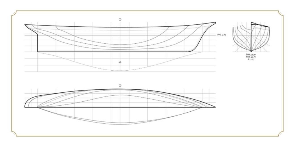
As you can (hopefully) see in the top-right drawing, the angle between the bottom of the ship and the side is greater than the previous drawing.
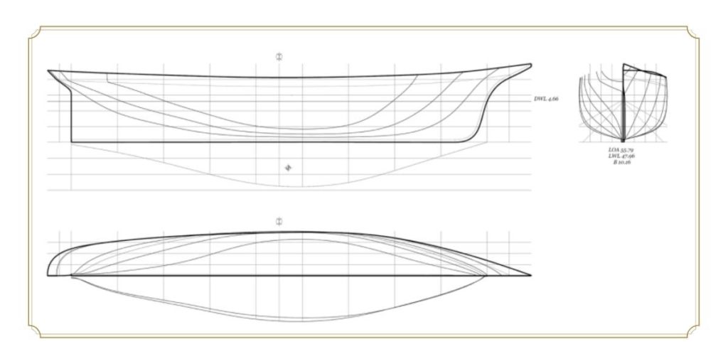
Hull 3 – A mixture of the two
The final shape to test was somewhere between Hull 1 and Hull 2. This would ensure the team covered all bases.
Testing the shapes
Enter, Cape Horn Engineering. Using Computational Fluid Dynamics (CFD), the three hull shapes were modelled in different circumstances:
- Upright sailing in 4, 6, 8, 10 and 12 knots of speed
- Heeling angles of 6 degrees and 12 degrees with 4, 8 and 12 knots of speed
- Drift angles of 3 degrees and 7 degrees with 4, 8 and 12 knots of speed
For those of you who are visual learners, alas this was not exact physical models with a water tank and wind machine. This was all on a spreadsheet. Although the three hulls are now models in Rhino, a program which shows you different elements of the design.
Conclusions (the physics part)
After these hulls were put to the test, it became clear that Hull 1 performed best! Particularly in winds less than 12 knots, there was 40% less resistance on Hull 1 than the other options. Interestingly enough, this was the empirical verification of an old rule of thumb of the academy that states that hull shapes with more deadrise (more V-shaped) are typically aimed for high speeds but tend to perform worse when sailing slower when compared to a “rounder opponent”. All in all, this means that in lighter winds, H1 will still be able to sail without disturbance to the way it sails.
To double check this, the team pulled out the estimated sail area necessary for upwind sailing, to see whether the side force that was generated would be balanced. H1, once again, came out tops as it offers the highest side force-to-drag ratio out of the three designs. Furthermore, H1 also allows maintaining CLR at more favorable astern positions and, due to its shape, sails with lower drafts in comparison to the remaining candidates (for the same displacement).
CLR: The (C)enter of (L)ateral (R)esistance is the center of pressure of the hydrodynamic forces acting on the hull. Proper Sail Balance is achieved by getting CLR in the correct relation to the (C)enter of (E)ffort, which is the center of the area of the sails.
Finally, it is crucial to mention that, as in life, no decision should be made based on a single criterion. Selecting the adequate hull shape for EcoClipper was no exception. In this regard, apart from the valuable insight that the CFD study provided, there were other strong arguments in favour of H1, namely, its smaller length should translate into lower construction costs, its high GT-to-length ratio could not be neglected and was one of the best candidates in terms of useful area in the lower cargo deck (quite important for stability, logistics and ship operations).
GT: (G)ross (T)onnage is a measure of the ship’s overall internal volume/capacity
So despite testing more “modern” hull designs, the original shape has stood the test of time. They really knew what they were doing back then. There is something to be said for learning from the past.
What’s next?
The team has put the final design into Rhino, which provides multiple overlays. This means that they can perfect the General Arrangement and sail plan. The rigging, line and sail plans will be put into 2D drawings.
The use of CFD has solidified the choice of extending the original Noach design. Through this, the team have been able to test the sailing capabilities of the EcoClipper500 as much as possible save from actually building the ship. It’s shown that the EcoClipper500 will sail as fast as some of the modern clipper ships of today, and of 100 years ago.